Nozzles
Vessel Nozzles
ASME pressure-vessel penetrations for inlet, outlet, instrument, manway and cleanout service.
Range overview
Specification and supply scope
Vessel nozzles are engineered penetrations in pressure equipment. The range covers flush, hillside, self-reinforced, shell, tangential, instrument and manway configurations, supplied as flanged, threaded or butt-weld connections. Designs are reviewed against ASME Section VIII Division 1 and project specifications for reinforcement, weld detail and NDE.
- Product types
- 8
- Documents
- 10
- Supply mode
- Made to order
Stock on request
Selection note: ASME Section VIII Div. 1, ASME B16.5, ASTM A106 / A182 / A312. Final dimensions and materials are confirmed on the order acknowledgement and, where required, the certified drawing.
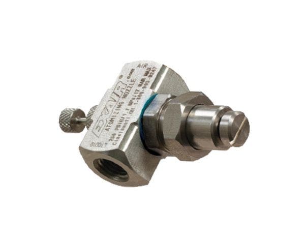
Type 01 · ASME Section VIII Div. 1
Flush Nozzle
Flanged vessel connection with a bore flush to the internal shell surface.
Typical applications
- Pharmaceutical vessels
- Food and beverage tanks
- Drain and outlet connections
- Clean-in-place systems
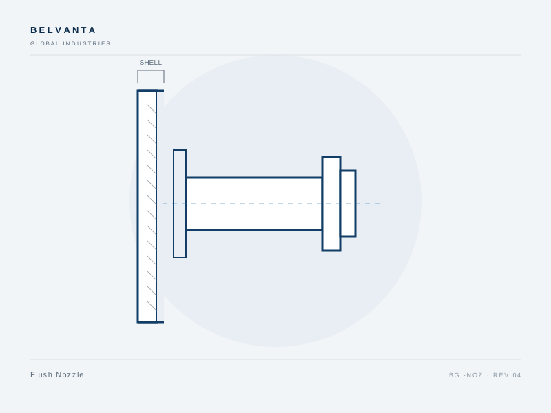
Flush nozzles terminate at the internal shell surface, minimizing product hold-up and eliminating a protruding lip. They are used for drain, inlet and outlet connections where cleanliness or flow continuity matters.
- Bore flush with internal shell surface
- Minimizes product hold-up and cleaning dead spots
- Flanged, butt-weld or threaded connection
- Reinforcement pad supplied where required
- Standards
- ASME Section VIII Div. 1 · ASME B16.5 · ASTM A106 / A182
- Materials
- ASTM A106-B · ASTM A182 F304L · ASTM A182 F316L
Specification
| Size range | 1/2–24 in |
|---|---|
| Pressure class | Class 150–2500 |
| Connection | Flanged, butt weld, threaded |
| Schedule | 40, 80, XXH or specified |
| Reinforcement | Pad or integral, per ASME VIII |
| Inspection | Dimensional, weld prep, NDE on request |
Ordering range
| Size | Schedule | Connection | Material | Part number |
|---|---|---|---|---|
| 2" | 40 | Flanged 150 | F316L | BGI-FN-0200-40-F316L |
| 4" | 40 | Flanged 150 | F316L | BGI-FN-0400-40-F316L |
| 6" | 80 | Butt weld | A106-B | BGI-FN-0600-80-A106 |
| 8" | 80 | Flanged 300 | A106-B | BGI-FN-0800-80-A106 |
Type 02 · ASME Section VIII Div. 1
Manway Nozzle
Large-diameter access opening with cover, davit and sealing arrangement.
Typical applications
- Pressure vessels
- Storage tanks
- Reactors
- Inspection openings
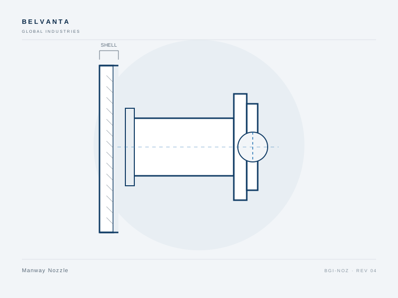
Manway nozzles provide personnel access for inspection, cleaning and maintenance. The assembly includes a reinforced shell opening, a bolted or hinged cover, a spiral wound gasket and, where specified, a davit arm for safe cover handling.
- Large-diameter access opening
- Bolted, hinged or quick-access cover
- Davit arm for cover handling
- Spiral wound or rubber gasket sealing
- Standards
- ASME Section VIII Div. 1 · ASME B16.20 · ASTM A516 / A105
- Materials
- ASTM A516-70 · ASTM A105 · ASTM A182 F316L
Specification
| Size range | 18–24 in |
|---|---|
| Pressure class | Class 150–300 |
| Cover type | Bolted, hinged, davit |
| Gasket | Spiral wound or rubber profile |
| Reinforcement | Integral or pad, per ASME VIII |
| Inspection | Dimensional, fit-up, NDE on request |
Ordering range
| Size | Class | Cover | Material | Part number |
|---|---|---|---|---|
| 18" | 150 | Bolted | A516-70 | BGI-MW-1800-150-A516 |
| 20" | 150 | Hinged | A516-70 | BGI-MW-2000-150-A516 |
| 24" | 150 | Bolted | F316L | BGI-MW-2400-150-F316L |
| 24" | 300 | Davit | A516-70 | BGI-MW-2400-300-A516 |
Type 03 · ASME Section VIII Div. 1
Pressure Vessel Nozzle
General-purpose flanged or welded penetration for pressure-vessel service.
Typical applications
- Process vessels
- Separators
- Scrubbers
- Heat exchangers
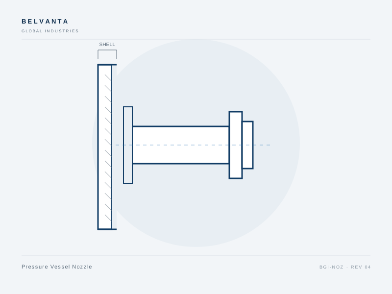
Pressure vessel nozzles are the standard connection for inlets, outlets, vents and drains on ASME vessels. They are supplied with reinforcement calculated for the shell and nozzle geometry, and with weld details suited to the specified NDE.
- Reinforcement calculated to ASME VIII
- Flanged, butt-weld or socket-weld connection
- Available with thermal sleeves
- Weld details for RT or UT examination
- Standards
- ASME Section VIII Div. 1 · ASME B16.5 · ASTM A106 / A182
- Materials
- ASTM A106-B · ASTM A182 F304L · ASTM A182 F316L
Specification
| Size range | 2–24 in |
|---|---|
| Pressure class | Class 150–900 |
| Connection | Flanged, butt weld |
| Schedule | 40, 80, XXH or specified |
| Reinforcement | Pad or integral, per ASME VIII |
| Inspection | Dimensional, weld prep, NDE on request |
Ordering range
| Size | Schedule | Connection | Material | Part number |
|---|---|---|---|---|
| 4" | 40 | Flanged 150 | A106-B | BGI-PVN-0400-40-A106 |
| 6" | 80 | Flanged 300 | A106-B | BGI-PVN-0600-80-A106 |
| 8" | 80 | Butt weld | F316L | BGI-PVN-0800-80-F316L |
| 10" | 40 | Flanged 150 | F316L | BGI-PVN-1000-40-F316L |
Type 04 · ASME Section VIII Div. 1
Hillside Nozzle
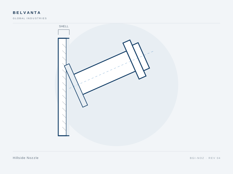
Angled penetration for connections that must follow a shell contour or flow path.
Typical applications
- Tank and vessel inlets
- Tangential flow connections
- Retrofit penetrations
- Internals support
Hillside nozzles enter the shell at an angle rather than perpendicular to the surface. They are used where geometry, flow direction or internals require an inclined connection, and are supplied with a contoured saddle or pad for a proper weld fit.
- Angled penetration to suit shell geometry
- Contoured saddle or pad for weld fit
- Common 15°, 30°, 45° and 60° orientations
- Flanged or butt-weld termination
- Standards
- ASME Section VIII Div. 1 · ASME B16.5 · ASTM A234 / A182
- Materials
- ASTM A234 WPB · ASTM A182 F316L
Specification
| Size range | 2–8 in |
|---|---|
| Angle | 15°, 30°, 45°, 60° |
| Connection | Flanged, butt weld |
| Weld preparation | Contoured saddle or pad |
| Reinforcement | Per ASME VIII |
| Inspection | Dimensional, fit-up, NDE on request |
Ordering range
| Size | Angle | Connection | Material | Part number |
|---|---|---|---|---|
| 2" | 45° | Flanged 150 | A234 WPB | BGI-HN-0200-45-A234 |
| 3" | 30° | Butt weld | A234 WPB | BGI-HN-0300-30-A234 |
| 4" | 45° | Flanged 150 | F316L | BGI-HN-0400-45-F316L |
| 6" | 60° | Butt weld | F316L | BGI-HN-0600-60-F316L |
Type 05 · ASME Section VIII Div. 1
Instrument Nozzle
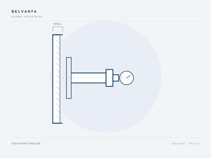
Small-bore connection for pressure, temperature and level instruments.
Typical applications
- Pressure transmitters
- Temperature gauges
- Level instruments
- Sampling points
Instrument nozzles provide a dedicated small-bore penetration for transmitters, gauges, thermowells and level devices. They are supplied with the specified thread or flange, and can include a thermowell or coupling as a single welded assembly.
- Small-bore instrument connection
- Threaded, flanged or socket-weld termination
- Thermowell and coupling options
- Compact reinforcement for shell openings
- Standards
- ASME Section VIII Div. 1 · ASME B1.20.1 · ASTM A106 / A182
- Materials
- ASTM A106-B · ASTM A182 F316L
Specification
| Size range | 1/2–2 in |
|---|---|
| Connection | NPT, socket weld, flanged |
| Schedule | 80 or specified |
| Thermowell | Integral or separate, on request |
| Reinforcement | Per ASME VIII |
| Inspection | Dimensional, thread gauge |
Ordering range
| Size | Schedule | Connection | Material | Part number |
|---|---|---|---|---|
| 1/2" | 80 | NPT | A106-B | BGI-IN-0050-80-A106 |
| 3/4" | 80 | NPT | A106-B | BGI-IN-0075-80-A106 |
| 1" | 80 | Flanged 150 | F316L | BGI-IN-0100-80-F316L |
| 2" | 80 | Flanged 150 | F316L | BGI-IN-0200-80-F316L |
Type 06 · ASME Section VIII Div. 1
Self-Reinforced Nozzle
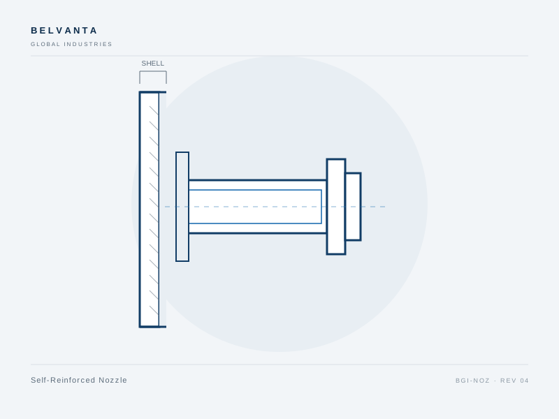
Heavy-wall nozzle that provides reinforcement without a separate pad.
Typical applications
- High-pressure vessels
- Cyclic service
- Compact equipment
- Retrofit connections
Self-reinforced nozzles use a heavier wall than the connecting pipe to provide the required area replacement. This avoids a separate reinforcement pad, reduces weld length and is well suited to cyclic or high-pressure service.
- Reinforcement integral to the nozzle wall
- No separate pad or saddle
- Reduced weld length and inspection burden
- Suitable for high-pressure and cyclic duty
- Standards
- ASME Section VIII Div. 1 · ASME B16.5 · ASTM A106 / A182
- Materials
- ASTM A106-B · ASTM A182 F316L
Specification
| Size range | 4–12 in |
|---|---|
| Pressure class | Class 300–900 |
| Schedule | 80, XXH or calculated |
| Reinforcement | Integral wall, no pad |
| Connection | Flanged, butt weld |
| Inspection | Dimensional, UT on request |
Ordering range
| Size | Schedule | Connection | Material | Part number |
|---|---|---|---|---|
| 4" | 80 | Flanged 300 | A106-B | BGI-SRN-0400-80-A106 |
| 6" | 80 | Flanged 300 | A106-B | BGI-SRN-0600-80-A106 |
| 8" | XXH | Butt weld | A106-B | BGI-SRN-0800-XXH-A106 |
| 10" | XXH | Flanged 600 | F316L | BGI-SRN-1000-XXH-F316L |
Type 07 · ASME Section VIII Div. 1
Shell Connection Nozzle
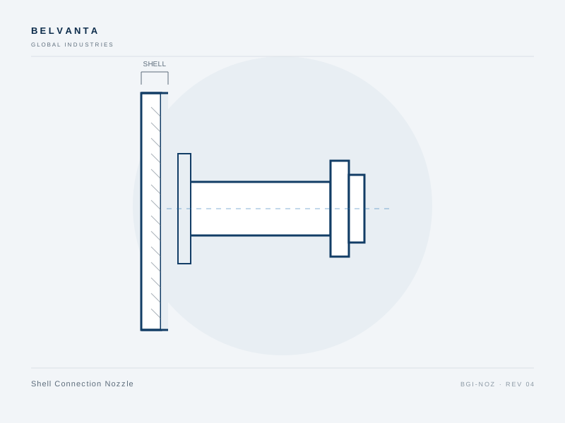
Nozzle with an integral pad for shell connections in stainless and alloy equipment.
Typical applications
- Stainless vessels
- Alloy process equipment
- Corrosive service
- Clean-in-place vessels
Shell connection nozzles combine the nozzle neck and a contoured reinforcement pad in one assembly. They are used on stainless and alloy vessels where a separate pad would add a crevice or complicate weld inspection.
- Integral reinforcement pad
- Contoured to the shell outside diameter
- Reduced crevice risk in corrosive service
- Stainless and alloy construction
- Standards
- ASME Section VIII Div. 1 · ASME B16.5 · ASTM A312 / A182
- Materials
- ASTM A312 TP304L · ASTM A312 TP316L · ASTM A182 F316L
Specification
| Size range | 2–8 in |
|---|---|
| Pressure class | Class 150–300 |
| Connection | Flanged, butt weld |
| Reinforcement | Integral contoured pad |
| Material | 304L, 316L, alloy on request |
| Inspection | Dimensional, PMI, NDE on request |
Ordering range
| Size | Schedule | Connection | Material | Part number |
|---|---|---|---|---|
| 2" | 40 | Flanged 150 | F304L | BGI-SCN-0200-40-F304L |
| 3" | 40 | Butt weld | F304L | BGI-SCN-0300-40-F304L |
| 4" | 40 | Flanged 150 | F316L | BGI-SCN-0400-40-F316L |
| 6" | 80 | Butt weld | F316L | BGI-SCN-0600-80-F316L |
Type 08 · ASME Section VIII Div. 1
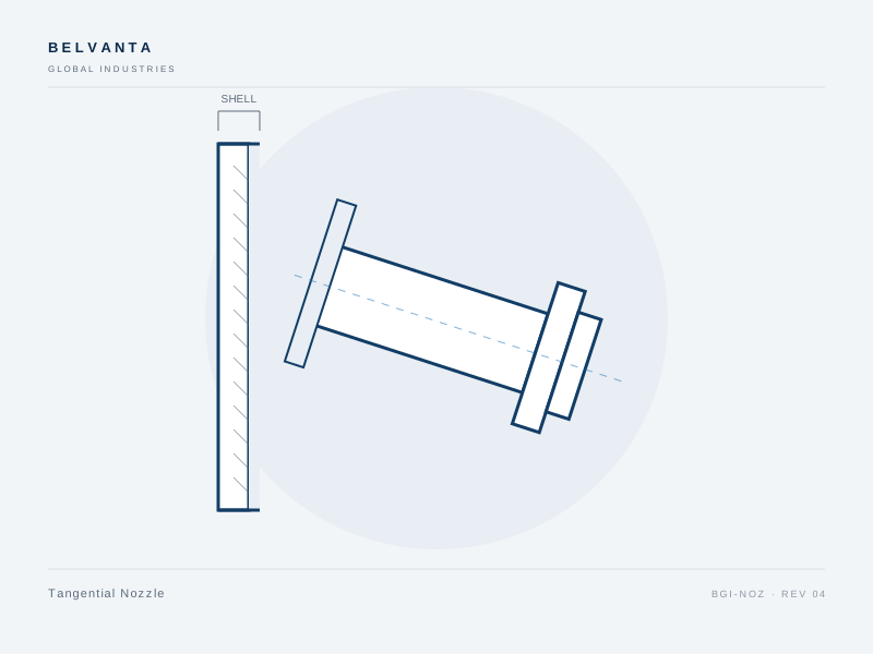
Tangential Nozzle
Nozzle oriented tangentially to the shell for swirl, mixing or separation duty.
Typical applications
- Cyclone and separator inlets
- Mixing vessels
- Gas-liquid contact
- Swirl-generating systems
Tangential nozzles introduce or withdraw fluid along the shell tangent, creating a swirl component for mixing, separation or gas-liquid contact. Orientation and entry angle are specified by the process design and verified during fabrication.
- Tangential orientation for swirl and mixing
- 15° and 30° entry angles available
- Butt-weld or flanged termination
- Fit-up verified against vessel datum
- Standards
- ASME Section VIII Div. 1 · ASME B16.5 · ASTM A312 / A182
- Materials
- ASTM A312 TP316 · ASTM A182 F316L
Specification
| Size range | 4–12 in |
|---|---|
| Orientation | Tangential, 15° or 30° entry |
| Connection | Flanged, butt weld |
| Reinforcement | Per ASME VIII |
| Material | 316, 316L, alloy on request |
| Inspection | Dimensional, orientation, NDE on request |
Ordering range
| Size | Angle | Connection | Material | Part number |
|---|---|---|---|---|
| 4" | 15° | Butt weld | F316 | BGI-TN-0400-15-F316 |
| 6" | 15° | Flanged 150 | F316 | BGI-TN-0600-15-F316 |
| 8" | 30° | Butt weld | F316L | BGI-TN-0800-30-F316L |
| 12" | 30° | Flanged 150 | F316L | BGI-TN-1200-30-F316L |
Documentation
Range documents
Datasheets, overviews and general arrangement drawings for this range. Controlled copies are issued with each order.
| Document | Type | Scope | Revision | Date | Action |
|---|---|---|---|---|---|
| Vessel Nozzles — Product Overview4 pages · PDF | Product overview | Nozzles · Vessel Nozzles | Rev. 04 | 15 Sept 2026 | Download |
| Vessel Nozzles — General Arrangement Drawing1 page · PDF | Drawing | Nozzles · Vessel Nozzles | Rev. 03 | 15 Sept 2026 | Download |
| Flush Nozzle Datasheet2 pages · PDF | Datasheet | Nozzles · Vessel Nozzles · Flush Nozzle | Rev. 04 | 15 Sept 2026 | Download |
| Manway Nozzle Datasheet2 pages · PDF | Datasheet | Nozzles · Vessel Nozzles · Manway Nozzle | Rev. 04 | 15 Sept 2026 | Download |
| Pressure Vessel Nozzle Datasheet2 pages · PDF | Datasheet | Nozzles · Vessel Nozzles · Pressure Vessel Nozzle | Rev. 04 | 15 Sept 2026 | Download |
| Hillside Nozzle Datasheet2 pages · PDF | Datasheet | Nozzles · Vessel Nozzles · Hillside Nozzle | Rev. 04 | 15 Sept 2026 | Download |
| Instrument Nozzle Datasheet2 pages · PDF | Datasheet | Nozzles · Vessel Nozzles · Instrument Nozzle | Rev. 04 | 15 Sept 2026 | Download |
| Self-Reinforced Nozzle Datasheet2 pages · PDF | Datasheet | Nozzles · Vessel Nozzles · Self-Reinforced Nozzle | Rev. 04 | 15 Sept 2026 | Download |
| Shell Connection Nozzle Datasheet2 pages · PDF | Datasheet | Nozzles · Vessel Nozzles · Shell Connection Nozzle | Rev. 04 | 15 Sept 2026 | Download |
| Tangential Nozzle Datasheet2 pages · PDF | Datasheet | Nozzles · Vessel Nozzles · Tangential Nozzle | Rev. 04 | 15 Sept 2026 | Download |
Verification
Documented at every release
Material, dimensional and pressure records are matched to the order before shipment. Certificates and test reports are available on request.
Quality and verificationMaterial traceability
Heat-number matched mill certificates and EN 10204 3.1 on request.
Dimensional inspection
Bore, face, bolt circle and envelope checked to drawing.
Pressure testing
Hydrostatic or pneumatic testing to the order specification.
Documented release
Inspection record, packing list and certificate package.
Related ranges
Continue through the catalog
Adjacent product lines are often specified together. Review the related range or open the full product index.
Request a quotation
Send the duty, we will confirm the configuration.
Provide size, pressure class, material, connection and quantity. For critical service, include the project specification, drawing or NDE requirements.