Flanges
Pipe Flanges
ASME B16.5 flanges for welded, threaded and bolted pipe connections in carbon and stainless steel.
Range overview
Specification and supply scope
Pipe flanges are the primary bolted connection in process piping. The range covers weld neck, slip-on, blind, lap joint, socket weld and threaded configurations in Class 150 through Class 2500, with raised-face, flat-face and ring-type joint options. Each flange is supplied with dimensional inspection records and heat-number traceability.
- Product types
- 6
- Documents
- 8
- Supply mode
- Made to order
Stock on request
Selection note: ASME B16.5, ASME B16.47, ASTM A105 / A182. Final dimensions and materials are confirmed on the order acknowledgement and, where required, the certified drawing.
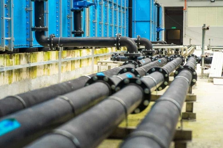
Type 01 · ASME B16.5
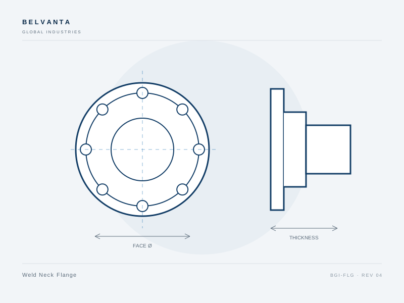
Weld Neck Flange
Butt-welded flange with a tapered hub for high-pressure and cyclic service.
Typical applications
- High-pressure process piping
- Steam and condensate
- Hydrocarbon service
- Cyclic duty
The weld neck flange transfers pipe stress through a tapered hub and a butt-weld connection, making it the preferred choice for high-pressure, high-temperature and cyclic piping. The bore matches the pipe schedule to reduce turbulence and weld inspection is straightforward.
- Tapered hub distributes stress into the pipe wall
- Butt-weld connection suitable for radiography
- Raised-face, flat-face and RTJ options
- Bore matched to pipe schedule
- Standards
- ASME B16.5 · ASME B16.47 · ASTM A105 / A182
- Materials
- ASTM A105 · ASTM A182 F304L · ASTM A182 F316L · ASTM A350 LF2
Specification
| Size range | 1/2–24 in (larger on request) |
|---|---|
| Pressure class | Class 150–2500 |
| Face type | Raised face, flat face, RTJ |
| Connection | Butt weld |
| Temperature | -29 to 425 °C (material dependent) |
| Inspection | Dimensional, visual, PMI on request |
Ordering range
| Size | Class | Face | Material | Part number |
|---|---|---|---|---|
| 2" | 150 | RF | A105 | BGI-WN-0200-150-A105 |
| 4" | 300 | RF | A105 | BGI-WN-0400-300-A105 |
| 6" | 600 | RF | F316L | BGI-WN-0600-600-F316L |
| 8" | 900 | RTJ | F316L | BGI-WN-0800-900-F316L |
| 12" | 1500 | RTJ | A105 | BGI-WN-1200-1500-A105 |
Type 02 · ASME B16.5
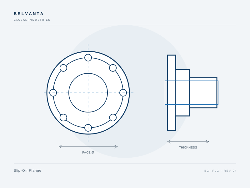
Slip-On Flange
Economical flange that slips over the pipe and is fillet-welded in place.
Typical applications
- Utility piping
- Low-pressure process lines
- Water and wastewater
- HVAC and cooling
Slip-on flanges slide over the pipe and are attached with two fillet welds. They offer lower installed cost and easier alignment than weld neck flanges, with adequate strength for many low- and medium-pressure services.
- Lower cost than weld neck construction
- Easier field alignment before welding
- Suitable for low- and medium-pressure service
- Raised-face and flat-face options
- Standards
- ASME B16.5 · ASTM A105 / A182
- Materials
- ASTM A105 · ASTM A182 F304L · ASTM A182 F316L
Specification
| Size range | 1/2–24 in |
|---|---|
| Pressure class | Class 150–900 |
| Face type | Raised face, flat face |
| Connection | Fillet weld |
| Temperature | -29 to 425 °C (material dependent) |
| Inspection | Dimensional, visual |
Ordering range
| Size | Class | Face | Material | Part number |
|---|---|---|---|---|
| 2" | 150 | RF | A105 | BGI-SO-0200-150-A105 |
| 4" | 150 | RF | F316L | BGI-SO-0400-150-F316L |
| 6" | 300 | RF | A105 | BGI-SO-0600-300-A105 |
| 8" | 300 | RF | F316L | BGI-SO-0800-300-F316L |
Type 03 · ASME B16.5
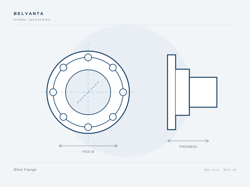
Blind Flange
Solid flange for isolating or terminating a pipe, valve or vessel connection.
Typical applications
- Line isolation
- Hydrotest boundaries
- Vessel closures
- Pipeline termini
Blind flanges close off piping, valves and vessel connections. They are available with raised-face, flat-face and ring-type joint sealing surfaces and can be drilled or tapped for instruments and drain connections on request.
- Positive isolation of line ends and test boundaries
- Raised-face, flat-face and RTJ sealing
- Optional tapped connections for instruments or drains
- Available with lifting lugs on larger sizes
- Standards
- ASME B16.5 · ASME B16.47 · ASTM A105 / A182
- Materials
- ASTM A105 · ASTM A182 F316L · ASTM A350 LF2
Specification
| Size range | 1/2–24 in |
|---|---|
| Pressure class | Class 150–2500 |
| Face type | Raised face, flat face, RTJ |
| Connection | Bolted |
| Temperature | -29 to 425 °C (material dependent) |
| Inspection | Dimensional, visual, PMI on request |
Ordering range
| Size | Class | Face | Material | Part number |
|---|---|---|---|---|
| 2" | 150 | RF | A105 | BGI-BL-0200-150-A105 |
| 4" | 300 | RF | A105 | BGI-BL-0400-300-A105 |
| 6" | 600 | RF | F316L | BGI-BL-0600-600-F316L |
| 8" | 900 | RTJ | F316L | BGI-BL-0800-900-F316L |
Type 04 · ASME B16.5
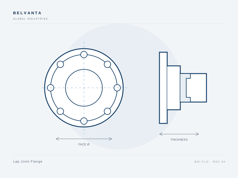
Lap Joint Flange
Two-piece flange and stub end assembly for easy bolt-hole alignment.
Typical applications
- Stainless piping
- Alloy process lines
- Tight installation spaces
- Frequent disassembly
Lap joint flanges use a stub end welded to the pipe and a loose flange that rotates into position. The design simplifies bolt-hole alignment in tight spaces and allows the flange material to be selected independently of the wetted stub end.
- Rotating flange simplifies bolt alignment
- Stub end can be a different alloy from the flange
- No weld at the flange face
- Common in stainless and alloy piping
- Standards
- ASME B16.5 · ASTM A105 / A182
- Materials
- ASTM A105 · ASTM A182 F304L · ASTM A182 F316L
Specification
| Size range | 1/2–24 in |
|---|---|
| Pressure class | Class 150–900 |
| Face type | Raised face, flat face |
| Connection | Stub end butt weld |
| Temperature | -29 to 425 °C (material dependent) |
| Inspection | Dimensional, visual |
Ordering range
| Size | Class | Face | Material | Part number |
|---|---|---|---|---|
| 3" | 150 | RF | F316L | BGI-LJ-0300-150-F316L |
| 4" | 300 | RF | F316L | BGI-LJ-0400-300-F316L |
| 6" | 150 | RF | F316L | BGI-LJ-0600-150-F316L |
| 8" | 300 | RF | A105 | BGI-LJ-0800-300-A105 |
Type 05 · ASME B16.5
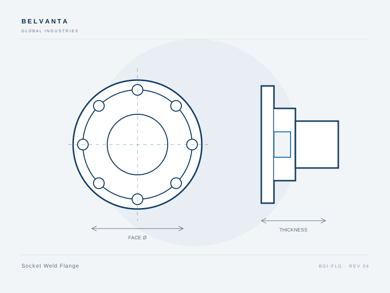
Socket Weld Flange
Compact flange for small-bore high-pressure piping with a socket weld connection.
Typical applications
- Small-bore high-pressure lines
- Instrument piping
- Hydraulic systems
- Steam tracing
Socket weld flanges are used on small-bore, high-pressure lines where a full-penetration butt weld is impractical. The pipe enters a recessed socket and is fillet-welded, providing a strong connection with good alignment.
- Compact small-bore connection
- Good alignment without backing rings
- Suitable for high-pressure utility and instrument lines
- Available in Class 300–1500
- Standards
- ASME B16.5 · ASTM A105 / A182
- Materials
- ASTM A105 · ASTM A182 F316L
Specification
| Size range | 1/2–4 in |
|---|---|
| Pressure class | Class 300–1500 |
| Face type | Raised face, RTJ |
| Connection | Socket weld |
| Temperature | -29 to 425 °C (material dependent) |
| Inspection | Dimensional, visual, weld prep check |
Ordering range
| Size | Class | Face | Material | Part number |
|---|---|---|---|---|
| 1/2" | 300 | RF | A105 | BGI-SW-0050-300-A105 |
| 1" | 600 | RF | A105 | BGI-SW-0100-600-A105 |
| 2" | 900 | RF | F316L | BGI-SW-0200-900-F316L |
| 3" | 1500 | RTJ | F316L | BGI-SW-0300-1500-F316L |
Type 06 · ASME B16.5
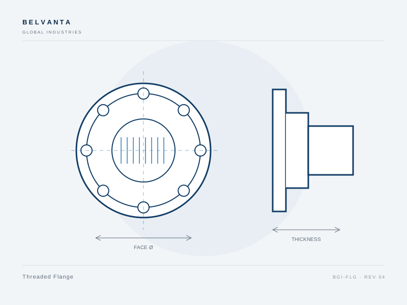
Threaded Flange
Tapped flange for small-bore connections where welding is not practical.
Typical applications
- Utility stations
- Instrument connections
- Maintenance tie-ins
- Non-welded assemblies
Threaded flanges are tapped to NPT or BSP and used on small-bore utility, instrument and maintenance connections. They avoid hot work and allow rapid assembly, with sealant or tape specified for the service.
- No welding required
- Suitable for utility and instrument connections
- NPT and BSP threads
- Available in carbon and stainless steel
- Standards
- ASME B16.5 · ASME B1.20.1 · ASTM A105 / A182
- Materials
- ASTM A105 · ASTM A182 F316
Specification
| Size range | 1/2–4 in |
|---|---|
| Pressure class | Class 300–600 |
| Thread | NPT, BSP |
| Connection | Threaded |
| Temperature | -29 to 425 °C (material dependent) |
| Inspection | Dimensional, thread gauge |
Ordering range
| Size | Class | Thread | Material | Part number |
|---|---|---|---|---|
| 1/2" | 300 | NPT | A105 | BGI-TH-0050-300-A105 |
| 1" | 600 | NPT | A105 | BGI-TH-0100-600-A105 |
| 2" | 300 | NPT | F316 | BGI-TH-0200-300-F316 |
| 3" | 600 | BSP | F316 | BGI-TH-0300-600-F316 |
Documentation
Range documents
Datasheets, overviews and general arrangement drawings for this range. Controlled copies are issued with each order.
| Document | Type | Scope | Revision | Date | Action |
|---|---|---|---|---|---|
| Pipe Flanges — Product Overview4 pages · PDF | Product overview | Flanges · Pipe Flanges | Rev. 04 | 15 Sept 2026 | Download |
| Pipe Flanges — General Arrangement Drawing1 page · PDF | Drawing | Flanges · Pipe Flanges | Rev. 03 | 15 Sept 2026 | Download |
| Weld Neck Flange Datasheet2 pages · PDF | Datasheet | Flanges · Pipe Flanges · Weld Neck Flange | Rev. 04 | 15 Sept 2026 | Download |
| Slip-On Flange Datasheet2 pages · PDF | Datasheet | Flanges · Pipe Flanges · Slip-On Flange | Rev. 04 | 15 Sept 2026 | Download |
| Blind Flange Datasheet2 pages · PDF | Datasheet | Flanges · Pipe Flanges · Blind Flange | Rev. 04 | 15 Sept 2026 | Download |
| Lap Joint Flange Datasheet2 pages · PDF | Datasheet | Flanges · Pipe Flanges · Lap Joint Flange | Rev. 04 | 15 Sept 2026 | Download |
| Socket Weld Flange Datasheet2 pages · PDF | Datasheet | Flanges · Pipe Flanges · Socket Weld Flange | Rev. 04 | 15 Sept 2026 | Download |
| Threaded Flange Datasheet2 pages · PDF | Datasheet | Flanges · Pipe Flanges · Threaded Flange | Rev. 04 | 15 Sept 2026 | Download |
Verification
Documented at every release
Material, dimensional and pressure records are matched to the order before shipment. Certificates and test reports are available on request.
Quality and verificationMaterial traceability
Heat-number matched mill certificates and EN 10204 3.1 on request.
Dimensional inspection
Bore, face, bolt circle and envelope checked to drawing.
Pressure testing
Hydrostatic or pneumatic testing to the order specification.
Documented release
Inspection record, packing list and certificate package.
Related ranges
Continue through the catalog
Adjacent product lines are often specified together. Review the related range or open the full product index.
Request a quotation
Send the duty, we will confirm the configuration.
Provide size, pressure class, material, connection and quantity. For critical service, include the project specification, drawing or NDE requirements.