Flanges
Specialty Flanges
Reducing and orifice flanges for line-size transitions and differential-pressure flow measurement.
Range overview
Specification and supply scope
Specialty flanges support line-size changes and flow measurement without additional spool pieces. Reducing flanges combine two line sizes in a single bolted connection. Orifice flanges provide tapped connections for orifice plates and differential-pressure transmitters, with jack screws and line markings supplied to ASME B16.36.
- Product types
- 2
- Documents
- 4
- Supply mode
- Made to order
Stock on request
Selection note: ASME B16.5, ASME B16.36, ASTM A105 / A182. Final dimensions and materials are confirmed on the order acknowledgement and, where required, the certified drawing.
Type 01 · ASME B16.5
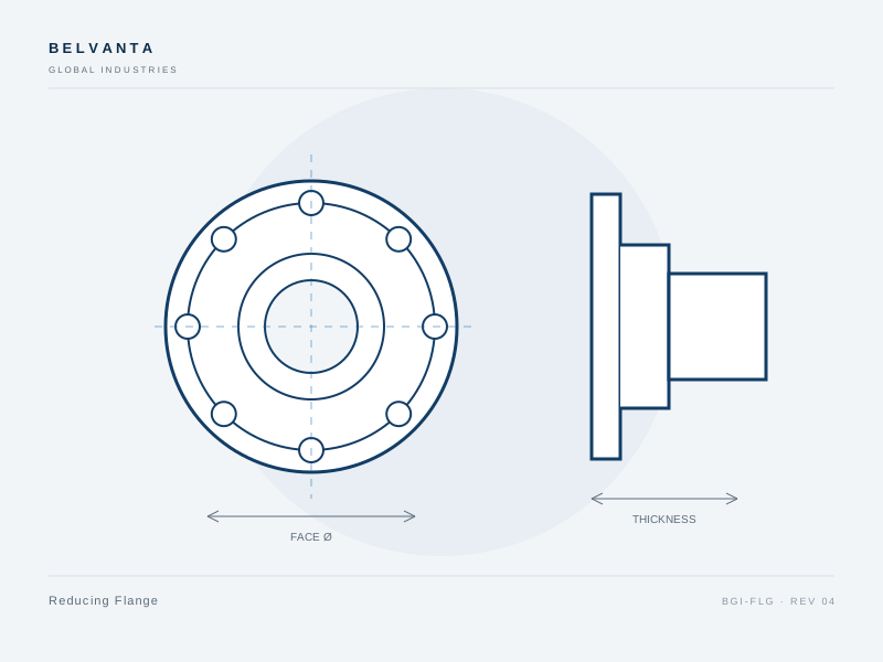
Reducing Flange
Single flange that transitions between two line sizes at a bolted connection.
Typical applications
- Pump suction and discharge
- Compressor connections
- Vessel and header transitions
- Metering runs
Reducing flanges combine a larger flange face with a smaller bore, eliminating a separate reducer and spool. They are used at pump suction, compressor, vessel and header connections where line size changes at the flange.
- Combines reducer and flange in one component
- Reduces bill of materials and joint count
- Available in concentric and eccentric bores
- Matched to ASME B16.5 dimensions
- Standards
- ASME B16.5 · ASTM A105 / A182
- Materials
- ASTM A105 · ASTM A182 F316L
Specification
| Size range | 2 × 1 to 24 × 20 in |
|---|---|
| Pressure class | Class 150–900 |
| Bore | Concentric or eccentric |
| Face type | Raised face, flat face |
| Temperature | -29 to 425 °C (material dependent) |
| Inspection | Dimensional, bore and face check |
Ordering range
| Size | Class | Face | Material | Part number |
|---|---|---|---|---|
| 4 × 2 | 150 | RF | A105 | BGI-RF-0402-150-A105 |
| 6 × 4 | 300 | RF | A105 | BGI-RF-0604-300-A105 |
| 8 × 6 | 300 | RF | F316L | BGI-RF-0806-300-F316L |
| 12 × 10 | 150 | RF | A105 | BGI-RF-1210-150-A105 |
Type 02 · ASME B16.36
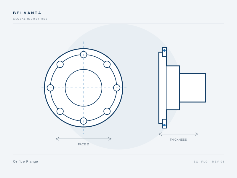
Orifice Flange
Tapped flange pair for orifice plates and differential-pressure flow measurement.
Typical applications
- Orifice metering runs
- Custody transfer
- Process flow control
- Utility measurement
Orifice flanges carry an orifice plate between two flanges and provide pressure taps for a differential-pressure transmitter. Jack screws, line markings and tap orientation are specified to ASME B16.36 and the metering requirement.
- Integral pressure taps for flow measurement
- Jack screws for plate removal
- Matched flange pair with plate and gaskets
- Raised-face and RTJ configurations
- Standards
- ASME B16.36 · ASME B16.5 · ASTM A105 / A182
- Materials
- ASTM A105 · ASTM A182 F316L
Specification
| Size range | 1–24 in |
|---|---|
| Pressure class | Class 300–2500 |
| Taps | 1/2 in NPT, flange or corner taps |
| Face type | Raised face, RTJ |
| Temperature | -29 to 425 °C (material dependent) |
| Inspection | Dimensional, tap position, plate fit |
Ordering range
| Size | Class | Face | Material | Part number |
|---|---|---|---|---|
| 2" | 300 | RF | A105 | BGI-OF-0200-300-A105 |
| 4" | 300 | RF | A105 | BGI-OF-0400-300-A105 |
| 6" | 600 | RF | F316L | BGI-OF-0600-600-F316L |
| 8" | 600 | RTJ | F316L | BGI-OF-0800-600-F316L |
Documentation
Range documents
Datasheets, overviews and general arrangement drawings for this range. Controlled copies are issued with each order.
| Document | Type | Scope | Revision | Date | Action |
|---|---|---|---|---|---|
| Specialty Flanges — Product Overview4 pages · PDF | Product overview | Flanges · Specialty Flanges | Rev. 04 | 15 Sept 2026 | Download |
| Specialty Flanges — General Arrangement Drawing1 page · PDF | Drawing | Flanges · Specialty Flanges | Rev. 03 | 15 Sept 2026 | Download |
| Reducing Flange Datasheet2 pages · PDF | Datasheet | Flanges · Specialty Flanges · Reducing Flange | Rev. 04 | 15 Sept 2026 | Download |
| Orifice Flange Datasheet2 pages · PDF | Datasheet | Flanges · Specialty Flanges · Orifice Flange | Rev. 04 | 15 Sept 2026 | Download |
Verification
Documented at every release
Material, dimensional and pressure records are matched to the order before shipment. Certificates and test reports are available on request.
Quality and verificationMaterial traceability
Heat-number matched mill certificates and EN 10204 3.1 on request.
Dimensional inspection
Bore, face, bolt circle and envelope checked to drawing.
Pressure testing
Hydrostatic or pneumatic testing to the order specification.
Documented release
Inspection record, packing list and certificate package.
Related ranges
Continue through the catalog
Adjacent product lines are often specified together. Review the related range or open the full product index.
Request a quotation
Send the duty, we will confirm the configuration.
Provide size, pressure class, material, connection and quantity. For critical service, include the project specification, drawing or NDE requirements.